My design includes the well used twin tube P/S probe in the first diagram with that of the AOA probe in the second.

 The AOA works by measuring changes in pressure of two pressure ports. one facing at an angle above the relative airflow and one at an angle below it. As the angle of attack increases the pressure in the lower port increases as the pressure in the upper port drops. This change can be measured on a differential pressure gauge calibrated for various speeds and AOAs ie. approaching the stall.
The upper port can be tapped off the pitot line, in my design the pitot line feeds both the ASI and the AOA. The other side of the AOA is a port facing 45' down, the same as the commercial probe above and I included a static probe to complete the set.
First I manufactured the tubes out of 5mm brass tubing from the local hobby supply. Bent to 45' with a break line bender and soldered together with spacers made of brass offcuts.

Here is the 3 tubes soldered together. I chose to put the pitot in the middle so it was in undisturbed air at all angles of attack. The lower tube will later be trimmed flush with the bottom of the probe (roughly in line with the bend in the pitot tube). It doesn't really matter if the static is in turbulent air.

Here it is again complete.

Here you can see the piece of steel aerofoil tubing I used as a plug to make my mould. I contemplated laying FG over the steel tube and then withdrawing it after curing but thought it would be more difficult to set the probes in place.

Used plaster to make the first half of the mould. What I haven't shown is how I made this first half. I buried the steel tube as close to 1/2 deep in clay as I could and then covered with the first half of the plaster. When this was dry I inverted it, removed the clay, painted with petroleum jelly as a release agent and then filled with plaster again.

Here is a shot of the second plaster in place.

Once dry I turned it out and split the two halves apart and removed the steel plug.

First I manufactured the tubes out of 5mm brass tubing from the local hobby supply. Bent to 45' with a break line bender and soldered together with spacers made of brass offcuts.

Here is the 3 tubes soldered together. I chose to put the pitot in the middle so it was in undisturbed air at all angles of attack. The lower tube will later be trimmed flush with the bottom of the probe (roughly in line with the bend in the pitot tube). It doesn't really matter if the static is in turbulent air.

Here it is again complete.

Here you can see the piece of steel aerofoil tubing I used as a plug to make my mould. I contemplated laying FG over the steel tube and then withdrawing it after curing but thought it would be more difficult to set the probes in place.

Used plaster to make the first half of the mould. What I haven't shown is how I made this first half. I buried the steel tube as close to 1/2 deep in clay as I could and then covered with the first half of the plaster. When this was dry I inverted it, removed the clay, painted with petroleum jelly as a release agent and then filled with plaster again.
Here is a shot of the second plaster in place.

Once dry I turned it out and split the two halves apart and removed the steel plug.
I then carved a relief in both halves so I had some meat and flat surfaces to enable me to mount it. Can you see the obvious stuff-up (the first of many I'm sure)

Yes the carved reliefs are on the same side where they should be opposing.
Easily fixed with a little more carving and some clay to fill the OOPS.
Tube assembly in place, aligned and stopped with clay.

Stood up and ready to fill. Extra holes in the top to make it simpler to fill.


End profile showing the aerofoil cross section. Even more efficient when you think I'm attaching it at 45' to the airflow.

Out of the Mould and smoothed to shape. will cover with a couple of light layers of BID for strength.

This is roughly where it will be located. I am trying to maximise the distance away from the influence of the wing while protecting it from too many bumps from onlookers by sitting it behind the leading edge.

Covered with a couple of layers of BID for added strength and now installed.

Stood up and ready to fill. Extra holes in the top to make it simpler to fill.

Not a 100% seal on those tubes, this dripped for nearly 2 hours while the resin went off. At the beginning I just scooped it up and put it back in at the top. This filler is non structural.

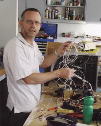
Yours truly scooping, and scooping and ... ... ...
Open up the mould to have a look. I like what I see. Now all I have to do is pry it out of the other half without damaging it. Clearly visible is the clay plug at the bottom to stop the resin falling through.
Open up the mould to have a look. I like what I see. Now all I have to do is pry it out of the other half without damaging it. Clearly visible is the clay plug at the bottom to stop the resin falling through.

End profile showing the aerofoil cross section. Even more efficient when you think I'm attaching it at 45' to the airflow.

Out of the Mould and smoothed to shape. will cover with a couple of light layers of BID for strength.

This is roughly where it will be located. I am trying to maximise the distance away from the influence of the wing while protecting it from too many bumps from onlookers by sitting it behind the leading edge.

Covered with a couple of layers of BID for added strength and now installed.
And another from the front showing the AOA inlet.


No comments:
Post a Comment