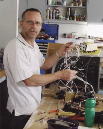
This is a shot of the mount the original builder made. His instructions to me was to inspect and test this part. Not that he did not trust his work but that it is such a vital part. As it turns out I had an accident wheeling the boat around my garage which bent the tubes attaching the NLG socket. I sought the advice of an engineer mate of mine who also happens to be building a plane. The outcome was that the original mount, besides my damage, had a few possible flaws in the welds. The decision easily made ... remanufacture the mount. I would then be sure of the quality and materials. (US 4130 is better quality than Chinese 4130 apparently).
Drawings for the O-200 on a KR2S
First step was to make an accurate jig from the drawings. Cross checking to the original mount I found it to be quite accurate. Could have made out of plywood for a 1 of but I was going for accuracy and I thought others could borrow it. New top plate and you could use it for other engines also (future upgrade?)
After completing the jig I slipped the old mount onto it and lo and behold it fit quite nice.

Now to set up the mount for the new work. You can see the firewall jig on the workbench with threaded rods fitted. Top of the photo is the engine plate which has been adjusted for the desired mount depth. The plans call for 11.5" but mine was 12" probably adjusted based on a W&B calculation. The base and then engine plate are levelled with a digital level (not shown) then the top plate is aligned to the base using a plumb-bob. When I made the jig I put a hole for the bob string and a punch mark in the base plate. Minor adjustments had to be made using turnbuckles as can be seen in later photos. Also, after consulting others in the KR-net I set my mount for 0' offset both vertically and horizontally. My research shows some build in an offset to dial out torque issues at low speeds but the KR is a quick beast and the benefit of straight thrust at high speed outweighs the loss of low speed trim. Anyway 99% of my flying will be at speed.
Misalignment can easily be seen with the plumb-bob .
Fast forward I have welded the 5/8" 0.120 wall 4130 tube to AN970-6 washers. If I were to do this again I would have made these out of plate 4130 for a few reasons; 1- the nickel coating on the washers causes issues when welding so needs to be removed, 2- these washers are a little soft, 4130 or HT plate would be better, 3- they are only 1.6mm thick, I would have preferred something a smidge over 2mm, and 4- You could make the diameter a little larger. It just so happens the 5/8" 0.120 tube has an ID of 0.385", perfect for AN-6 bolts at 0.375". I used scrap 10mm bolts for all the weld jobs so I didn't damage my final bolts.
Here I have made a practice run using 16mm dowel. Saved making mistakes with real tube.
In this shot you can see the digital level and the adjustment cross bracing.
This shot shows the top plate being levelled and also the hole I made for the plumb-bob string.
All tubes were mitred using a nifty free little program called Tubemitre. only problem is that it is in mm but it worked great.
http://www.ozhpv.org.au/resources/shed/tubemiter.html
First finished mitre. Looks great hey? They are quite easy to begin with but get more difficult as 2 or more meet at one point. I did the welds in 2 waves, I set up the first 4 tubes and then got those welded in. the second set were then fitted around the first.
Here is a shot of a tube that fits where a first tube is already welded into place.
2 tubes fitted together.
I had all welds done by a professional welder. Tip here, try to keep all the tubes perfectly clean both inside and out.
A few shots of the finished mount. A work of art if I do say so myself. When I offered the mount up to the already drilled firewall the bolts slipped straight into place.
And fitted to the engine great too.
Last thought ... the plans for the mount were obviously designed to fit with the original 20A generator installed. I was going all electric so upgraded to the later Autolite (Ford based) 50A alternator which I had lovingly restored at great expense. Problem was the girth of the alternator is a smidge greater than the generator and the mount would no longer fit. The diagonal anti-torque brace (seen here under the new unit) would have had to be adjusted by about 1/2" to make it fit. I have seen these bent on other mounts or you could relieve the tube and weld in a patch (this tube carries minimal force). I chose instead to buy a more modern miniature alternator that was still 50A but fit perfectly. Bonus is that it is internally regulated. Anybody want an old generator, reconditioned alternator both with brand new electronic regulators. Oh well, we live and learn.